Plumbing questions answers tips and tricks.
Flue thru roof detail.
With the pipe in a vertical position trace around the pipe using a pencil.
The base flashing extends onto the roof a minimum of 4 and is soldered to the ventilator.
Wall with self terminating parapro paraflex 531 liquid flashing.
Paraguard expansion joint roof to wall with parasolo flashing.
Gutter brackets are required to be at least one gauge heavier than gutter stock.
Roof area divider curb type.
This detail illustrates a method of flashing a ventilator on a sloped roof.
Download free high quality cad drawings blocks and details of roof vents.
Attach wood nailer to wall or deck with suitable.
Paraguard expansion joint roof to roof with parasolo flashing.
Fd17 and interior drains or through curb scuppers to drain the roof.
Detail for attachment to metal panel siding or fascia.
If the vent pipe isn t installed properly the roof may leak through or around the pipe penetration leading to costly repairs.
The roofing material shingles asphalt paper etc should overlap the top edge up.
Downspout strap detail 1 4 dia.
X 5 8 bolt brass alum.
Step 1 go into your attic.
Plumbing questions answers tips and tricks.
Wall flashing with coated metal edge.
Roof flashing details index fd01 interior roof drain detail fd02 interior drain with gravel stop detail fd03 scupper roof drain detail.
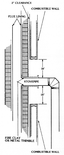
Care should be taken to follow manufacturers installation and safety clearance instructions.
Large flashings are formed with a hook edge on the top and sides and cleated to the sheathing at 12 o c.
This detail for cmu installation only.
Common penetration details include soil vent pipes hot pipes from boiler flues or log burners electrical cables for air conditioning units extraction ducting and tracks for mechanical window cleaning systems.
The penetration will be oval to have a round pipe exit.
Reply to vertical flue through a polycarb roof.
Position the vent pipe up to the bottom of the roof.
See table 2 a roof flash ing is placed down over the pipe and adjusted so it fits tightly against the roof with the pipe section held in a position maintaining the 1 inch minimum clearance from combustibles.
Typical single storey flue system through framed chimney with cap flashing flat ceiling with open roof cavity space and pitched roof.
Heat welded walkway.
Wall base termination detail.
This is a graphical display of a typical freestanding 150mm diameter flue system.

